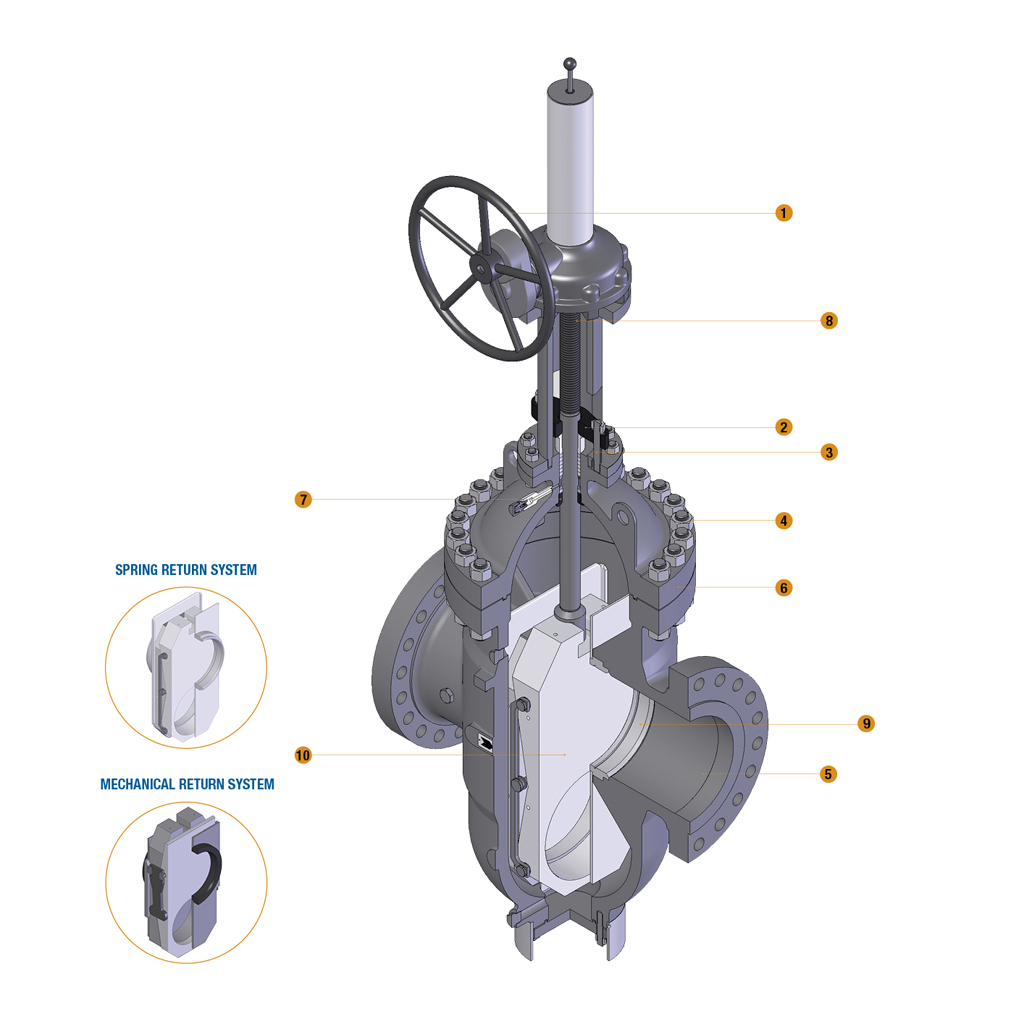
GLAND AND FLANGE
They are in forged steel and are supplied in two pieces, self aligning design to permit the gland to descend parallel to the stem even if the eyebolts are unevenly tightened.
The double block and bleed feature of this valve and the seats fixed in the body require always to provide a body pressure relief system. Usually, an external piping with a check valve is supplied to bleed upstream any overpressure may be trapped in body cavity. A manual drain/vent valve or connection is always suggested. A lantern ring is supplied only upon request, in this case the stuffing box shall be drilled, tapped and fitted with an ¼” NPT plug or grease fitting. Special actuator /handwheel extension can be arranged in order to lift the actuation position, and as well drain / bleed / injection connections can be extended up to the operator level for underground pipeline application.
Pipeline valves are best fit for vertical stem / horizontal flow installation. Special cases can be evaluated and developed on request.
The spoked handwheel is fabricated from steel pipe. The hub is coupled with the yoke sleeve by means of a a key. Larger valves are equipped with a bevel or spur gear gearbox unit.
They are in forged steel and are supplied in two pieces, self aligning design to permit the gland to descend parallel to the stem even if the eyebolts are unevenly tightened.
The forged steel gland bolts are of the eyebolt type which can be swung outward for ease of gland repacking. They are fixed to the bonnet by hinge pins.
Bonnet studs and nuts are manufactured from alloy steel to the relevant ASTM standard. The body to bonnet connection is designed according to ASME VIII DIV 1 standard.
The body is in carbon or stainless steel and is available in many other CRA. It is carefully designed for total reliability and simple maintenance. The basic dimension, i.e. wall thickness, face to face and flanges comply with the relevant ASME and API standards, in particular the API 6D standard. The body-to-bonnet flange is circular. Standard “through conduit” design allows for passage of scrapers and spheres. The body is basically supplied with renewable seats. Bosses are provided for drain taps or by-pass piping. The internal surfaces in contact with the fluid can be fully lined or cladded for improved corrosion or erosion resistance.
As the body, the bonnet is in carbon or stainless steel and is available in many other CRA. It is machined to accept yoke sleeve and incorporates a stuffing box dimensioned in accordance with the API standard. Lifting lugs can be provided integrally cast on the bonnet surface.
The bonnet bushing is part of the valve trim. Its design allows on request safe valve repacking without valve’s bleeding or draining using auxiliary seals. It doesn’t allow the classical backseating position in contact with the stem head, but if the application allows to use O-R or lip seals, it is possible to include an auxiliary seal for repacking.
The stem is part of the trim and is available in a wide range of material in accordance to API 600 or customer’s requirements. The stem is provided with a T-shaped head. The stem is highly finished to minimize friction and prevent damage to gland packing. The thread is trapezoidal ACME type. Because of the intrinsic design of the valve, it is not possible to create a backseating position.
Welded-in seat rings are supplied as a standard, and floating seats can be supplied as well. The rings are part of the trim of the valve and are usually hardfaced or coated by tungsten carbide.
The concave and convex disc are part of the trim. They are forged in stainless steel. They are connected to the stem by means of a T joint. Special attention is given to the seating surfaces which are grounded and lapped, and can be hardfaced or coated with tungsten carbide.